
LS7 GTO Build - Tribute for Chris Erberich
Background Information
On July 3rd of 2006, Sgt. Christopher Erberich died after his helicopter went down on a routine training mission in Savannah, Georgia. He did 5 tours in Iraq, 1 in Afghan and came back unscathed. A fellow drag racer and automotive enthusiast, he was a friend and family to many people. After this tragic event, his wife Stephanie Erberich decided to take his prized joy and build it the way he would've wanted it. Stephanie contacted us at Tiberio Performance to see what we could do to help her, this is the log of this build.
October 3rd, 2006
It began yesterday.
I had to disassemble the motor to remove the crank. Tomorrow, it gets sent out to Thunder Racing to have the reluctor ring changed so I can use as much of the GTO harness as possible. The cylinder heads, intake, and throttle body are off to porting already. The stock camshaft will be replaced with a grind yet to be chosen.
Today, I got the LS2 out and started looking at the other modifications that need to take place. Looks like the oil tank will need to be modified/fabricated to fit where the battery used to be. The oil pan is going to need some modifications too. It needs to clear the rack in the rear and will have to go with a remote filter location to clear the pinion on the steering rack. The sump on the oil pan will have to remain in the existing location (centered) as all the oil passages are cast into the oil pan itself. Because of this, the crossmember will need some serious re-work. I'll have to notch it a good amount and re-enforce it like my 3rd gen F-Body when I put a Steff's oil pan on it. I will post more pics as things change.
More later, just thought you guys might be interested.
Took the LS7 out of the crate and got it on an engine stand. It will be going in the 2005 GTO that is in the background.


In a couple of hours, it looked like this:

Ottrod asked:
Is there a way that one could modify / plumb the GTO pan for dry sump to avoid cutting the car?
Anything is possible, but it would require a re-design of the oil pump and hard plumbed internal lines. The oil pump is larger than an LS2 but mounted in the same location and crank driven. It mates to the passages that are cast in the oil pan. I'll post picks of the pan and pump tomorrow.
gotzaGTO asked:
How is this going to be controlled? I mean computer that is? And what ever you guys do to make this work, will all the GTO functions work??? i.e. gauges, DIC and so on...
Reluctor ring on the crank gets changed to LS2 spec (52 vs 58 I think) so the GTO computer can read the crank. Cam gear gets changed to LS2 single bump gear so it can read the cam. FI connections are the same, as are the rest of the sending units / sensors, and the locations are the same. The orig. harness and commputer will be retained so all should still work.
October 4th, 2006
Didn't accomplish too much today. I had to help someone button up a cam removal among other things. I did make some cardboard templates and do a mockup.


As you can see, there are two inlets and one return on the pump that mate to the oil pan and gasket, also, as can be seen in the last picture, there is an internal pickup in the sump to handle splash oil. The ports to the oil pump are irregular shapes. Even if you could weld up the pump with fittings for hard plumbed lines the LS2 oil pan would require a re-work as the LS7 pan is longer in the front to accomodate the oil pump and the ports. The front cover is also pushed out further towards the front to mate to the longer pan and accomodate the pump.
But even as this is typed, I am still trying to think of a more simple method for the oil pan.
October 10th, 2006
Today is Chris's Birthday, an excellent day for an update.
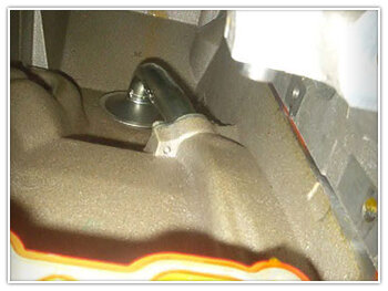
Didn't work on it much towards the end of last week, had some other jobs to finish, but had the plasma cutter out the last couple of days. The oil tank placement is roughed in and just have to fab up the brackets to mount it. The tank will have to be slightly modified with a scallop to make sure there is plenty of clearance to the front tire. The mounting brackets will also include a shield, just to make sure nothing can get kicked into it. Also drew up a a sketch of the new washer tank. Had to remove the factory washer tank in order to mount the oil tank. I'll post pictures as I start to get things finished.
The big news is, there will be no frame modification. We are going to fabricate a custom pan from the LS2 oil pan. This will eliminate the need to modify the frame and relocate the oil filter. The oil pan fabrication will start tomorrow as it is the biggest hurdle. Also fabbed up brackets for an engine oil cooler as the plumbing for it was ordered along with the motor. It's going to be pretty sweet. It will look factory. Once again, I'll take lots of pictures of the process and post up.
Done a good amount of research and we are going to be able to use the stock harness and everything should work.
That's all for now. I'll get some pictures posted in the next couple of days.
October 17th, 2006
Sorry the updates have been few and far between but at the moment, as with most car projects of this type, I am waiting on parts. All the port work has been completed but I have not been able to pick them up yet. Pics, when I get them back. The crank is still at Thunder Racing and they are waiting for......you guessed it.....PARTS.
The valve train has been ordered, 248/254 on a 114. Should have a nice idle. I did finish the oil tank installation. I just need to make a filler/ splash panel for the remainder of the wheel well opening and a filler seal to go around the tank.
Pics below.


Now that the mounts are finalized, the tank has to be removed and a scallop cut and plate will go where the black marker lines are. Needs just a little bit more clearance for the fender apron.


I was able to use the 2 existing tank brackets and all I had to do was fab up a body attachment bracket for the lower tank mount.
greg'sgoat asked:
does the numbers on the LS7 cam = the same on a LS2 cam? Cause if so, that thing is HUGE.
No, I believe the LS7 cam is 211/230 566 lift, but I am not certain. All I know, that it is not going back in the motor.
November 16th, 2006
Been away for a while but then again there has not been much to report. Finally got a reluctor wheel for the crank and should have the crank back next week. I'll have the final mock-up on the oil pan tomorrow and I'll post some pics up at that time. In the meantime here are some pics of the ported heads, they have since been fully assembled with titanium retainers, 921 springs, ect . . . As promised, a pic of the trunk badge!

The cresent shape that has been highlighted by the flash in the intake bowl is a built in flow director to help begin the swirl process.

Excellent view of where the backside on the valve would be. Just did a mild clean-up of the exhaust port as the short side radius was just about perfect.


What can I say, I got bored. I took the "7" froms Doc's 5.7 badge and replaced the "6" from Chris' badge. I did have to separate the point from the "0" and move it over because there was to much space between the base of the "7" and the "0".
November 26th, 2007
Well, it's been a very productive Holiday weekend. A lot of work was accomplished on "The Magnificent 7". I know it sounds a little gay, but since I did the 7.0 Liter badge one of the guys at the shop, who's into cowboy movies, nicknamed it "The Magnificent 7" and it just has kind of stuck.
Got the crank shaft back Tuesday. Major thanks to Angie and Jeff at Thunder Racing. Had a minor hiccup but they got on top of things and expedited delivery. Thank you so much.

All the parts layed out and ready to install.

Had the cam shaft ground 2 degrees advanced. LSA is 114 and I degreed the cam in to make sure that intake centerline is 112.

Plenty of piston to valve clearance. About .120 on the intake and .150 on the exhaust.

The completed Short Block

Here's some photos of the internals for any of you that are into more of the design/tech aspect of this motor.


Nice shot of the piston and rod assembly. Race car parts all the way. Coated short skirt piston design with full floater. Check out the thickness/size of the rings, especially the oil ring. Definitely low tension and why this motor has to be a dry sump. They were thinking about weight reduction with everything. Short skirt piston, short thin wall wrist pin and the scallop on the sides of the small end of the forged connecting rod. Nice stuff throughout.
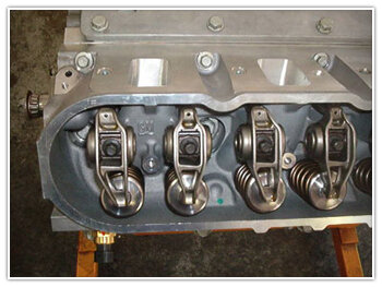
Nice view of the rocker arms, good comparison for the offset intake rocker, which allows for the nice big intake ports.
Here are some more:


Comparison of LS7 crank reluctor ring (top) and LS2 (bottom).
The LS7 ring not only has more teeth and different spacing, but it is also a single piece stamping. The LS2 ring, which is now shown installed on the LS7 crank is a 2 piece welded design.

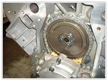
The LS7 cam gear has multiple raised sections vs. the LS2 with it's single raised arc. The LS2 cam gear has been installed in the LS7. Both the cam position sensor and the crank position sensor from the LS2 are bolt in swaps and will be used on the LS7 in order to maintain the current PCM and harness.
December 7th, 2006
Well, finally got the oil pan done and it fits like it was meant to be. Toughest part was fabing up the new pan pick-up. Making sure that it cleared the crank throws and the main studs. The rest of the motor went together without incident. Did have to do a minor trim on the very front of the windage tray to clear the new pick-up. Motor is complete and on the stand and the oil tank modification has been completed also. Hopefully my next post will include pictures of the motor in the car.

The working end of the new oil pan and the new sump pick-up. For those of you into retro, the retaining bolt for the pick-up is an official Pontiac 455 V8 oil pan bolt.

Here you can clearly see all that was used from the LS7 pan was the very front of the rail that mates to the oil pump. It is the portion that still has the cast finish. The inlet and the outlet tubes stand off the front now and the oil lines can be easily hooked up and gaurded by the now manditory skid plate.

The final test fit on the block.

The minor modification to the oil tank to make sure there is plenty of tire clearance.

The completed motor, ready for installation.
December 13th, 2006
Speaking of LS7 motors, it just so happens that ours is finally installed. Everything went pretty much as planned. Little bit of a suprise when I went to mate the transmission to the motor. Seems that the Corvette uses a different pilot bearing and location. No biggie, just had to remove the Vette bearing and install a GTO LS2 bearing.
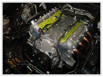
One freshly set LS7

Mocking up the new power steering pressure line

Starting to look more like a finished product.

The next issue to solve. The placement if the alternator and power steering drive are directly in the way of the air inlet tube. Have to move the filter assembly further forward with a slight angle.

A look at the oil pan from underneath.
Shouldn't be long now. Amazon hose made the new power steering line today and the parts that I need to make the oil lines will be in by Friday.
All that's really left to do is button up the install and get the battery in the trunk.
December 19th, 2006

Looks pretty good in there, doesn't it?
Oh and another thing, at 11:06 pm It Started and Ran for the first time.
grfperformance asked:
Are the power steering and alternator issues being caused by the longer crank snout?
Yes and no. When you purchase the crate motor it's supplied with the Corvette Balancer because it's the only car the motor currently is installed in. Although the balancer is not keyed to the crank, if it is removed, it still has to be marked in relation to the crank shaft and reinstalled in the same location. Unlike LS1, LS2, LS6 etc, the balancer pulley assembly is balanced to the crank shaft on an LS7. Even if you could use the LS2 GTO balancer, because of the longer crank and crank gear, the alternator, power steering, and associated brackets still do not work because the balancer is forward of the accessories. I looked into an aftermarket balancer that could have been made to work with the GTO accessories, but the cost of it was more than the cost of all the Corvette brackets, alternator, and power steering pump.
First of all I wanted to thank everybody for the kind words. It has been quite a project and it is still not over yet. I started it last night, open headers and I hooked the exhaust up this morning before I started it up again. The car has an SLP Loudmouth on it and it doesn't sound that much different than open headers. It does sound pretty mean though. Here's some more pictures of where I am at now.

Even when using the Corvette AC Compressor mount, I was able to retain the GTO compressor. In order to get the belt to line up, all I had to do was switch the pulley to a 6 rib. Now, the belt rides in the first 4 grooves with perfect alignment.


The oil lines at the pan and the tank.
Solved the air tube to alternator interference issue. After a little bit of fiddling around, I decided to cut the tube mid straight (where the silicone sleeve and clamps now are) and rotate the up-stream section about 90 degrees forward. This gave me a slight downward slope to the tube and also moved the MAF end further forward. Then all I had to do was trim the base of the air filter surround and lengthen the side bracket. Although the picture doesn't show it very well, there is plenty of clearance now.

December 28th, 2006
Well, here's the deal. Jeremy Formato came by on Christmas Eve and worked out some preliminary tune issues to make the car more driveable for the trip over to the dyno. Speaking of dynos, the car was dyno'd today. We found out quite early that the MAF was maxed out and we had to go to a speed density tune and the 1 3/4 headers are probably holding things back a little bit.
Long story short, SAE numbers were roughly 525/480. The car is an absolute animal to drive and with the SLP Loudmouth 1, it is obnoxiously loud. All in all, quite happy with the end result.
Big thanks to JoeyD for coming by and taking video and plenty of still pictures, which he should be posting up here soon. Hopefully the sound on the video does justice to how the car truly sounds.
Also thank you to Jeremy Formato for all the odd hour holiday tuning/help and a fantastic job at the dyno today.
Just a couple of loose ends to tie up this week and it'll be ready to deliver.
January 17th, 2007
DocGTO has been adding miles to the Spec 3 clutch to make sure it is broken in before the Bradenton Track Day Event. At the same time DocGTO has also been road testing it got 18.5 mpg average back from Tampa and 13.5 in the city. Coolent temp has been around 175-178 degrees. No problems at all...
More updates to come as the Second Annual All-GTO Track Day in Bradenton Florida comes around on the 21st of January. The LS7GTO will make its debut down the track and a special tribute to Chris Erberich will be made.
January 22nd, 2007
Yesterday was the big track day meet. It turned out amazing. The memorial went off without a hitch, first the cars were staged for the missing man formation as Doc gave a memorable tribute to Chris. Afterwards, Stephanie took the car down the track, as she drove the only sound you could hear was the LS7, the entire track was dead silent. It was quite a sight to behold. To you Chris:


And like the image above states, yes Doc took the car down for a personal best for the LS7 despite the DA being 2200 at one point. The car ran 11.48@120.5 with a 1.74 60’! Quite amazing for a cammed only LS7. With better weather and a bit more practice, the car is capable of much better.


